How to Wire a 4 Way Switch
You may have mastered wiring a 3 way switch but do you know how to wire a 4 way switch? Well...it's not too bad...especially if you understand 3-way switches. Four-way switches are used to control power to a light from three or more different locations. You must purchase switches labeled as 4-way switches rather than 3-way or normal light switches. 4-way switches can be quickly identified by the 4 screw terminals (in addition to the green/gnd screw terminal). Two of the terminals are brass and labeled "input", the other two are black and labeled "output". It is very important to pay attention to these as shown in the 4-way switch diagram.
When wiring a 4 way switch circuit as shown below, you will use two 3-way switches and one 4-way switch. If you wanted to add a fourth switch to the circuit you would need another 4-way switch wired in the middle in the same way as the first 4-way switch. You might ask, how can I wire a 4 way switch with regular light switches, or all 3 way switches, or all 4 ways switches? The answer is you can't. You must have a 3 way (3 terminal) switch on each end of the series and then a 4-way (4 terminal) switch in the center. If you don't have the right switches you need to get the right switches rather than trying for hours to somehow make it work. I only say that because I've seen people try to figure out ways to make it work, using the wrong switches, and they end up with switches that have to be in certain positions for other switches to work and it's a huge mess to straighten out.
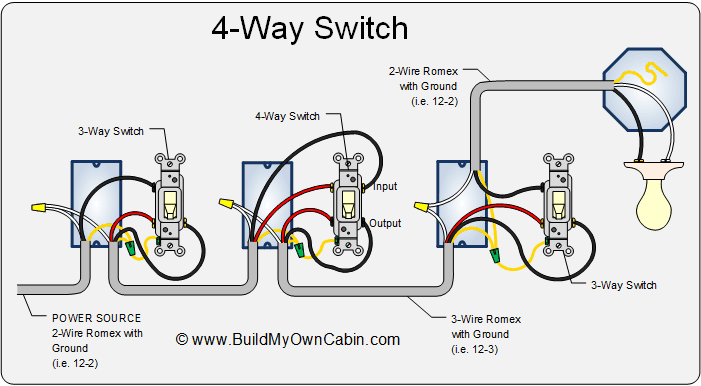
4-Way Switch Diagram - (pdf, 78kb)
How Four-Way Switches Work
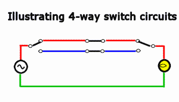
The animation above illustrates how a 4-way switch circuit works to control a light. The left-most switch is a three-way switch. The center switch is a four-way switch and the right-most switch is a three-way.
The animation is color coded to represent voltage states rather than colors of the actual wires you would use in an installation.
Red - represents hot or 120 volts.
Green - represents neutral or 0 volts.
Blue - represents floating wires which are neither 120 volts or 0 volts.
The voltage source is shown in the left of the animation and for the light to turn on you need the 120 volts to reach all the way to the lamp. Using different switch positions, a continuous circuit must be completed from the voltage source to the lamp. If the voltage is routed to a dead end the lamp will not light.
Click the icons below to get our NEC® compliant Electrical Calc Elite or Electric Toolkit, available for Android and iOS. The Electrical Calc Elite is designed to solve many of your common code-based electrical calculations like wire sizes, voltage drop, conduit sizing, etc. The Electric Toolkit provides some basic electrical calculations, wiring diagrams (similar to those found on this website), and other electrical reference data.